I don’t know whether it’s sentimentality or practicality – or maybe both – but I love Radio Shack. While there are stores and/or online vendors who offer a wider assortment of embedded devices and electronic components, their Radio Shack stores are everywhere, and the selection is good. And although the prices are higher than ordering directly from China, I can have a part or board in hand in 15 minutes if Radio Shack carries it. You’re buying the item + unbeatable convenience, and all things considered, it’s a pretty great deal.
Years ago, I bought a little multimeter kit from Radio Shack. I needed a multimeter, and I kind of wanted to “build it myself”. The ArcherKits are easy to assemble, with just enough soldering and small work to give you immense satisfaction every time you use it. 🙂
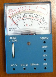
I’ve since upgraded multimeters to a nice digital model, but you know what I keep in my embedded device toolbox? My trusty old analog ArcherKit multimeter. It’s not fancy, but it’s nearly indestructible and it just works.
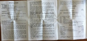
Just today, I couldn’t remember how to take a measurement that I rarely have call to make, and when I went to look for the operator’s manual, I couldn’t find it. Searching online didn’t help, either. I finally did locate it…but it occurred to me that others may find themselves in the same bind. And no one should have a great tool without having the instructions handy. So…below is a snapshot of the basic foldout of operating instructions. Simple, straightforward, and essential!
If you have an ArcherKit 28-4012A multimeter, I hope you’re still enjoying it as much as I am. When absolute digital precision is required, this little guy gets a well-deserved rest…but guess what sees the most action? 😉
Keep MAKING,
Mark
Related Posts:
- Please check back for related posts!
Tags: 28-4012A,
ArcherKit,
instruction,
manual,
multimeter,
operating,
Radio,
Shack
If you’ve worked (or played) much with Arduinos, you’ve probably run into “dead pins” – or wondered if you had. How can you tell which pins, if any, are unusable on an otherwise perfectly good board?
There are probably more precise ways of determining what is wrong, and perhaps even ways to repair some defects…but for those of us embedded folk who work far more with software than hardware, this is a quick way to confirm which pins don’t work properly with sufficient precision so you can label the board and move on. To quote Steve Jobs, “Real artists ship.” 🙂
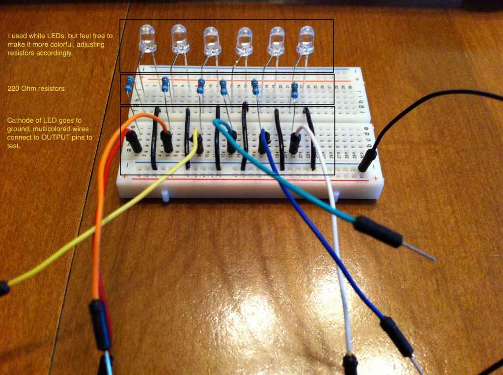
To test digital pins, you need to test both pinModes: INPUT and OUTPUT. (There is also INPUT_PULLUP, but that is only relevant if using the internal resistors vs. external ones.) I created two sketches, one to test pins with a call to digitalWrite() to light up connected LEDs, and one to read a switch using digitalRead(). Those are the software components necessary, and they’re available at my ArduinoPinTests GitHub repository.
The hardware portion of the test can be easily assembled as well. Here are the items I used; feel free to substitute similar components as desired:
- Solderless breadboards (2, one for each: input & output)
- LEDs (6)
- Resistors, 220 Ohm (6) (for output test board)
- Resistors, 10k Ohm (2) (for input test board)
- microtivity IM211 push-and-lock switch (for input test board)
- Necessary wires to put it all together
It has been said that a picture is worth a thousand words. Here are two thousand for you!
Digital Pins (In) Test Board
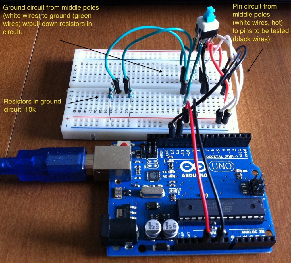
Digital Pins (Out) Test Board
The Bottom Line
If you have pins you think may be dead on your Arduino or clone board, grab some spare parts, visit my GitHub repo, and within minutes you can find out if/which pins are out of commission and get back to configuring devices and pounding out code. Now…back to business!
All the best,
Mark
Related Posts:
Tags: Arduino,
bad,
digital,
digitalRead,
digitalWrite,
github,
input,
output,
pinMode,
pins,
test


