Hecklers in Development
Code, coffee, & camaraderie. Collection, unordered. ;)

Or “How to build a portable self-powered, self-licking ice cream cone.”  😀


Portable IoT Demo


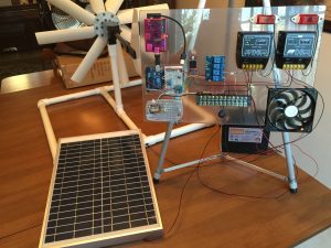
Several years ago, I started building what I referred to affectionately as a self-licking ice cream cone: a Renewable Energy (RE) system that powered the same IoT system that monitored it. I’ve given several talks about this system, both its hardware and its software stack, and there are so many useful (and scalable) lessons I’ve learned that I really enjoy sharing. Still learning those lessons too, btw.


Recently, Stephen Chin asked me if I could put together a portable RE IoT system to demo in the MakerZone at JavaOne this year. If a picture is worth a thousand words, a fully-built and on-premises demo must be worth at least a million, right? The idea intrigued me. Could I create a 100% fully-capable representation of a (my) real working system that would be small enough to transport to conferences and meaningful for attendees to see? Yes…yes, I thought I could.  🙂


It has been a lot of work fun!


There is much to tell, but we’ll stick to the high points for this post. More to follow.


Hardware List and Related Observations


For the portable configuration, here is the hardware I used:

  • One (1) 50W, 12V photovoltaic (PV) panel, bought via ebay
  • One (1) Cyber 250 wind turbine
  • One (1) 18Ah 12V deep cycle battery for energy storage and IoT system power
  • One (1) sheet of Lexan cut to size and edged, courtesy of Regal Plastics in St. Louis
  • One (1) Raspberry Pi, case, SD card, & wifi plug adapter – this serves as the IoT gateway device
  • One (1) 5V DC voltage regulator, allowing me to step down the 12V battery output to the 5V required by the Pi
  • One (1) Arduino Uno R3, solderless breadboard, combined mounting board – this represents an IoT endpoint
  • One (1) Adafruit INA219 high-side DC current sensor breakout
  • One (1) Virtuabotix DHT11 temperature & humidity sensor
  • One (1) 4 channel DC 5V relay to control physical devices
  • One (1) LED case cooling fan
  • One (1) interior/dome light to represent building interior lighting
  • Two (2) running lights to serve as loads for two RE inputs/charge controllers
  • Two (2) solar charge controllers**
  • One (1) 12 position terminal strip/wiring block
  • Numerous (?) solder joints, wires, and cables

** I was able to use solar charge controllers for both solar/PV and wind inputs because the wind turbine I selected produces 12V DC power (vs. the AC power output of many turbines) and has a blocking diode to prevent overspeeding, and thus turbine damage. These charge controllers also have load connectors, to which I attached lamps to maintain loads on the inputs, further reducing potential for overspeeding.


This configuration closely follows my permanent installation at my house, albeit at a much smaller scale. For transportability, I’m using only a single 18Ah 12V deep cycle battery instead of several larger-capacity 12V deep cycle batteries wired in parallel to form an energy storage array. And input sensors have been reduced from a full weather station providing temperature, humidity, rainfall, wind speed & direction, ambient lighting, and atmospheric pressure readings to (for the demo system) temperature and humidity. Power readings are comparable for both systems, although I’m using a separate INA219 sensor on the demo system vs. integrated power sensors in the permanent system’s weather circuitry. And my portable system has no actuators to open windows in my power-generation building like my permanent system does. Since the demo system is fully visible to viewers, there was no need to configure a camera for visual observation/checks as I did at home. In actuality, there are few substantive differences between my 24/7/365 production system and this portable demo. 🙂


One nice feature of this portable rig: as configured, it produces far more energy than it consumes, even with a fan providing the “wind” and venue lighting providing the “sun”. Power won’t be a problem.


Software and Related Observations


The software stack for the demo system is nearly identical to that of the production system, with minor changes being made to accommodate the minor differences in attached sensors and physical devices.


I developed software for the Arduino microcontroller to run in Autonomous Mode using sensible defaults, turning on heat when ambient temperature inside the power-generation building is too low, turning on a cooling fan when it’s too hot, and opening windows on opposite sides of the building when temps climb and no rain is present (no windows in the demo config, of course). The Arduino represents an IoT endpoint that regularly (1x/second) polls attached sensors, assembles their readings, and sends them “upstream” to the IoT gateway. It also processes any inputs received from the gateway and acts accordingly; if it receives a command to switch to Manual Override, the software then accepts and processes any subsequent (validated) commands from the gateway until directed to resume with Autonomous Mode.


For the IoT gateway, I used Linux and Java SE Embedded to create a secure and standards-based stack. Raspbian Linux allows me to use utilities like ssh and vnc and to set up startup scripts for the demo config…and since it ships with Java SE Embedded, I have easy access to developer tool support and libraries for everything from RESTful web services to Websocket, which I use for system/cloud communication. I used the JSSC (Java Simple Serial Connector) library to create a wired connection from gateway to endpoint, Pi to Arduino, establishing a reliable comm link within the remote IoT system.


IoT systems are great! But without a way to communicate with, control, and harvest meaningful data from those systems, their usefulness is severely constrained. To unleash the full value of an IoT system, you need the cloud. I used Java SE, Spring Boot, and Spring Cloud OSS to do the heavy lifting with an HTML5/JS user interface, all running on Pivotal Cloud Foundry. I’m still tweaking and expanding it (in my copious spare time 😉 ), but it’s effectively feature-complete…and with only minor differences (to accommodate the sensor/device differences) between the permanent and demo systems.


And…action!


More to Come


Come see me at JavaOne! This will be up and running in the MakerZone all week, so stop by to see it and chat with the crew there. If you have any questions, comments, or feedback of any kind, please ping me on Twitter at @MkHeck or leave a comment below. Hope to see you there!


Keep coding,
Mark


Share

Related Posts:


Tags: , , , , , , , , , ,

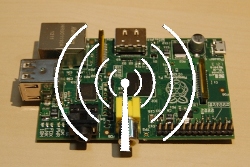
When I got my first Raspberry Pi Model B (not long after they first became available – remember when they only had 256M?!?), I wanted to configure it to use a wifi adapter. Even with approved, compliant adapters, this wasn’t for the faint of heart; many steps, scripts, and secret incantations were required to get everything to connect, even in the best of circumstances.


Fast-forward to today, when wifi adapter drivers are included in the base Raspbian build. It’s relatively simple to connect to wifi networks that broadcast their SSIDs. Ah, but what about those with hidden SSIDs? Not so much.


Many sites have documented ways to get around this. The problem is that I’ve tried several of them without success, so I always return to my original settings – and they still work just as well as the day I put them together. So to save myself (and hopefully you, if you’re reading this post!) a great deal of time in the future, here is the shortest path I’ve found to configuring your Raspbian-running Pi to connect to a wifi network that doesn’t broadcast its SSID.

raspberry-pi-wireless

The Secret Sauce Steps

0. Log into your Pi (default user ID: pi, default password: raspberry).

Edit the network interfaces file

1. cd /etc/network

2. sudo cp interfaces interfaces.orig (this makes a backup copy of your interfaces file)

3. sudo vi interfaces (feel free to use a different editor if vi isn’t your cup of tea)

4. Edit your interfaces file to look like this:


5. Save the interfaces file.


Edit wpa_supplicant

1. cd /etc/wpa_supplicant

2. sudo cp wpa_supplicant.conf wpa_supplicant.conf.orig

3. sudo vi wpa_supplicant.conf

4. Edit your wpa_supplicant file to look like this:


5. Save the wpa_supplicant.conf file.


NOTE: If you have another network entry in this file (e.g. for a guest network), be sure to place this line in its entry to prevent its use:


Test

  • sudo reboot
  • Login once prompted.
  • ifconfig -a

If it’s working properly, your wlan0 adapter will show a valid IP address, a number of bytes and packets received and sent (RX and TX), and several other useful bits of information.

That’s all, folks

I’ve used this with three different wifi adapters, and it’s worked every time. Hopefully, it will work for you as well.


If you found this useful (or not, clear or confusing, etc.), please let me know. Good luck, and enjoy your Pi!


Keep coding,
Mark

Share

Related Posts:


Tags: , , , , ,

I’ve been testing various “embedded platforms” lately to provide infrastructure for my IoT configurations. In doing so, I’ve installed and configured the GlassFish 4 Web Profile to run successfully on the Raspberry Pi Model B (512M). This post is not meant to be exhaustive or even necessarily prescriptive, but rather an iterative log of what I’ve done and do to configure a Raspberry Pi to “run with the big dogs”, i.e. Java Enterprise Edition (EE) 7.

GlassFish 4

Raspberry Pi Logo

Please check back (or subscribe to my RSS feed for IoT) to monitor updates. The Internet of Things (IoT) is a very dynamic space and will likely remain so for some time! The only constant…is change.  😀

Document version 1.3 (This number will change as I make updates and is for reference only)

Steps to Install/Configure GlassFish 4 on the Raspberry Pi

  1. Download the latest version of Raspbian Wheezy from here. You can install NOOBS, Arch, or some other distro, but I chose Raspbian. Note that this distro includes the Java SE 7 JDK, which simplifies things a bit. If you wish to use an previous Raspbian build that doesn’t already include the JDK, simply run “sudo apt-get update && sudo apt-get install oracle-java7-jdk” from your Pi shell.
  2. Make a bootable SD card by doing the following (on my Mac; Windows steps will vary a bit):
    1. Unzip/decompress the downloaded image from step 1
    2. Open a Mac terminal window
    3. Run “diskutil list” to see drives
    4. Plug SD card into SD card slot
    5. Again run “diskutil list” to see drives, now including the SD card
    6. Run “sudo diskutil unmountDisk /dev/diskn“, where n is the disk number of the SD card (as reported by diskutil)
    7. Issue the following command, being very careful to ensure the of= parameter points to the SD card! If not, you can overwrite something you’d rather not…like your boot drive: “sudo dd if=<path/name_of_Raspbian_image.img> of=/dev/diskn bs=1m”
    8. Once dd completes, issue “diskutil eject /dev/diskn” to eject the SD card
  3. Plug the SD card into the Pi, plug ethernet cable and power into the Pi to boot.
  4. At this point, you’ll need to determine current (dynamic) IP address of the Pi. I plugged in my Atrix Lapdock and did this “on the Pi”, but you can also use nmap or connect it to HDMI (TV) and USB keyboard.
  5. Run “sudo raspi-config” and set the following:
    1. Expand the file system to take the entire SD card (not just what the image initially does)
    2. Under Internationalisation Options, change Locale, Timezone, & Keyboard layout as desired
    3. Overclock to High (950MHz). I’ve tried Turbo, but it seems prone to flakiness & data loss…at least for me.
    4. Under Advanced Options, change Hostname to desired Pi name, Memory Split to 16 (as a server, we can skinny the GPU memory allocation to maximize “main” memory), and enable SSH. You can also “Update this tool” (raspi-config) to the latest version, never a bad thing.
    5. Select “Finish” to reboot the Pi & use the new settings
  6. Ensure the Pi has a static IP by doing the following (recommended for any server):
    1. Run “ifconfig -a” and “netstat -nr” on the Pi to gather the following information: current IP (if you want to keep it), netmask, gateway, destination, and broadcast. Jot these down.
    2. Make a backup of /etc/network/interfaces by running “sudo cp /etc/network/interfaces /etc/network/interfaces.orig
    3. Modify the interfaces file. I used vi, but use whatever editor you can & are comfortable with! The vi syntax is “sudo vi /etc/network/interfaces”
    4. Change the line that reads “iface eth0 inet dhcp” to “iface eth0 inet static” and add the following lines:
      • address 192.168.1.nnn (this is the IP address you want the Pi to have & keep)
      • netmask 255.255.255.0 (or whatever was shown in ifconfig -a above)
      • network 192.168.1.0 (or whatever was in the destination column, 2nd line from netstat -nr above)
      • broadcast 192.168.1.255 (as shown in ifconfig -a)
      • gateway 192.168.1.1 (or what was shown in either ifconfig or netstat)
    5. Save the file
    6. Reboot the Pi (“sudo reboot”)
    7. NOTE: You’ll also need to tell your network DHCP device/router that the IP address you statically assigned to the Pi is off-limits for assigning to another device
  7. Download GlassFish 4 Web Profile (or full EE platform) from here. I chose the Zip installer.
  8. Copy the GlassFish .zip file to the Pi (“scp glassfish-4.0-web.zip pi@raspi:.”). I have an entry in my Mac’s /etc/hosts that points “raspi” to the Pi’s static IP address.
  9. On the Pi, “install” GlassFish by doing the following:
    1. Run “sudo mkdir -p /app/glassfish” to create GlassFish app parent directory
    2. Run “sudo chown pi /app/glassfish” to assign directory ownership to the pi user. Not absolutely necessary, but you typically don’t want root to own everything (although honestly at this stage & for this install, it’s not critical)
    3. “cd /app/glassfish” as the pi user to change directories into the “install” directory
    4. Run “unzip ~/glassfish-4.0-web.zip” to extract the GF files into this directory
  10. Now to configure GF to allow for remote administration/configuration using its web console app:
    1. “cd /app/glassfish/glassfish4/bin”
    2. Run “./asadmin change-admin-password --user admin” to assign a password to the admin user. The admin password defaults to a blank password, a no-no for GF remote admin.
    3. Run “./asadmin start-domain” to start the default domain (which comes preconfigured in GF)
    4. Run “./asadmin enable-secure-admin” to enable remote administration using the web console
    5. In order to take utilize remote admin, stop the domain by running “./asadmin stop-domain”, then…
    6. Start the domain once more with “./asadmin start-domain”
  11. From your workstation/laptop, plug this into a browser address bar: “raspi:4848” (substituting the name of your Pi per your /etc/hosts file) or “192.168.1.n:4848″ (substituting the IP address or your Pi) to load the GF admin console
  12. Login and relish the fact that you now have a full Java EE 7 stack (or web profile) running on your Raspberry Pi server!

I’m capturing this from memory, so it’s possible I’ve missed a step I performed or have related it not-exactly-perfectly…but if you spot something that isn’t quite right or have questions, please let me know! I’ll update this document accordingly. YMMV (Your Mileage May Vary), especially if you’re using a Linux or Windows machine for your workstation, but hopefully, this will get you that much closer to your own tiny Java EE 7 stack for your own growing IoT empire.

All the best,
Mark

P.S. – Follow me on Twitter at @MkHeck for more Java/IoT adventures…yours and mine (and ours)!

Share

Related Posts:


Tags: , , , , , , , , , , , ,

Renewable energy (RE) has long been a passion of mine, but practically speaking, it simply hasn’t been cost-effective to implement at a personal level. Factoring in credits, location, type of RE, etc. can often tip the scale, but generally speaking, an investment in RE would require more commitment than simply “running the numbers.” No judgment here, I understand and appreciate both sides of that argument.


In recent years, though, things have changed. Not entirely, and not across the board even now…but with inexpensive (yet quality) RE equipment being produced in the US, China, and many locations throughout Europe, one can begin to experiment with RE on a much smaller scale and determine if/how it makes sense for your particular situation.


As a software engineer, I also work to integrate whatever I build into a more manageable, usable system. Physical computing promises many things, which I’ll coarsely lump into the term “better living” – but to do it right requires more than just assembling some hardware. The intersection of devices with software and the greater internet results in what is often termed the “Internet of Things”, or the IoT…and this is where the potential for “better living” can skyrocket, if things are properly integrated. It’s a small and limited example, but how much more useful is a fully-integrated system that is easily managed from anywhere on the planet than a complex system composed of numerous components…all of which must be monitored individually and manually?


For this post, we’ll focus solely upon one small portion of that integrated system: adding PV, or photovoltaic (solar) panels to a functioning small-scale RE system. Before these additions, the system consisted of:

  • Wind turbine
  • Deep-cycle battery bank
  • Arduino to control sensors, radio transceiver
  • Temp/humidity and current/voltage sensors
  • Radio transceiver, primarily for comm link to send readings

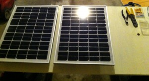
Now we’re adding a solar charge controller and initially, two 25W solar panels wired in parallel for a total of 50W maximum.


In future posts, I hope to elaborate on the software side because (as stated above) that is where the difference truly lies. For now, here are some pictures (and a very short video) of the PV addition:

Connecting PV Panel

Connecting the PV Panel


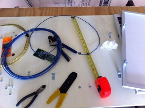
Assembly Of PV Board

Mounting the PV Panels to the Backing Board


Two Panels Mounted

Initial Two Panels Mounted


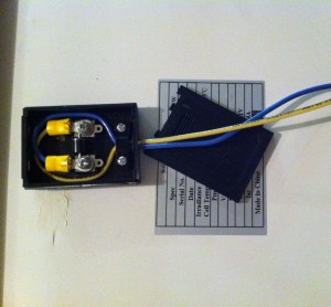
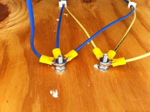
Wire Terminals On PV Board

Simple Wire Terminals on PV Board


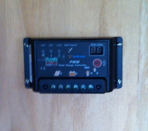
Charge Controller

Charge Controller Mounted, Not Yet Connected


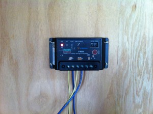
Charge Controller Working

Charge Controller Mounted AND Connected!
The “Sun” light indicates power from the panels;
the “Battery” light flashes while charging attached batteries.


And finally, a short video to give a glimpse of the PV portion of the system in action:

In future posts, I plan to provide more information about the “good stuff” (teaser: JavaFX, Java Embedded Suite, more Arduino, BeagleBone Black, wireless management, and more!), but a system must exist before it can be monitored and managed. As we continue to “build out” the system, those opportunities will only increase. Stay tuned, and please feel free to comment below or drop me a line. Thanks for visiting!


All the best,
Mark


Share

Related Posts:


Tags: , , , , , , , , , , , , , , , , , , , , , , , ,

Powered by Wordpress
Theme © 2005 - 2009 FrederikM.de, heavily modified by Mark Heckler
BlueMod is a modification of the blueblog_DE Theme by Oliver Wunder